2B.2.3 D.C. method
2B.2.3.1 General
The d.c. saturation method applies a d.c. voltage u(t) of such duration that saturation flux is reached. The flux measurement is derived according to equation (2B.11) given in 2B.2.1, where u(t) is the voltage across the terminals. See Figure 2B.10.
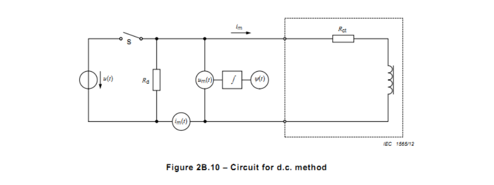
The applied voltage source shall be suitable to drive the current transformer into saturation.
The discharge resistor Rd shall be connected; otherwise the magnetizing inductance of the core may cause very high overvoltage when switch S is opened and the inductive current interrupted.
2B.2.3.2 Determination of the remanence factor KR
The test circuit according to 2B.2.3.1 shall be used.
Sometime after the switch S has been closed, the magnetizing current will be deemed to have reached its maximum value at which the secondary linked flux would remain constant. Before reaching the constant value, the curve must show a significant increase of the gradient, indicating saturation. The d.c. source shall be able to drive the transformer core into saturation without influencing the test results due to its limitations. This condition is fulfilled if the secondary linked flux achieves a stable value earlier than the magnetizing current.
The rising values of the magnetizing current and of the flux shall be recorded up to the time at which the values become constant, then the switch S will be opened.
Typical test records of the flux and of the magnetizing current are shown in Figure 2B.11.
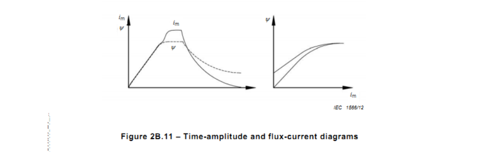
At the opening of switch S, a decreasing current flows through the secondary winding and the discharging resistor Rd. The corresponding flux value decreases, but may not fall to zero.
When a suitable magnetizing current has been chosen to achieve the saturation flux, the remaining flux value at the zero current shall be deemed to be the remanent flux.
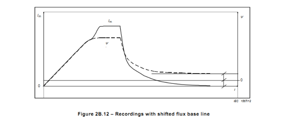
For a current transformer whose core has not been demagnetized before, the saturation flux and the remanent flux may be determined by an additional test in which the secondary terminals have been interchanged. The curve of secondary linked flux obtained hereby contains an offset of half of the apparently measured remanent flux value. Therefore, the zero line has to be shifted correspondingly, leading to corrected values of saturation flux and remanent flux. See figure 2B.12.